Nýjustu vörur


Hafðu samband við okkur
- Fjórða hæðin, A - A3 Zone, Aviation Business Area, Dongli Distrct, Tianjin, Kína.
- >Salesmanager@Coilwinding
Machinechina.com - +8613072088960


Hraðkomandi Toroidal Core Turns Prófari
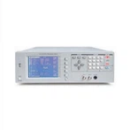
NAME: GW-901 EI transformer coil measuring instrument I. Overview This instrument is used for measuring the turns of various types of coils, such as motor windings, generator windings, transformers and transformer coils, relay coils, TV HV/LV converters, and auto ignition coils. Thanks to the...
Lýsing
NAME: GW-901 EI transformer coil measuring instrument


3.
|
|
Φ2mm |
Φ3mm |
Φ4mm |
Φ6mm |
Φ10mm |
|
|
0~300 coils |
±0 coils |
|||||
|
301~500 coils |
±1 coils |
|||||
|
501~5000 coils |
±0.3% |
±0.3% |
±0.2% |
±0.2% |
±0.2% |
|
|
5001~20000 coils |
-- |
±0.4% |
±0.2% |
±0.2% |
±0.2% |
|
|
20001~60000 coils |
-- |
-- |
±0.5% |
±0.5% |
±0.5% |
|
|
0~5000 coils |
0~20000 |
0~60000 coils |
||||
|
>2mm |
>3mm |
>4mm |
>6mm |
>10mm |
||
|
Less than or equal to 20mm |
Less than or equal to 30mm |
Less than or equal to 110mm |
||||
|
Less than or equal to 15mm |
Less than or equal to 25mm |
Less than or equal to 120mm |
||||
|
AC220V±10%, 50Hz±2Hz |
||||||
|
Environmental Temperature: +5 degree ~+35 degree , Relative Humidity: 85% below |
||||||
|
370 x 220 x 110 (mm) |
||||||
|
Approx. 7kg |
||||||
Notes: Coils less than 2000 coils shall be measured at a fast speed and coils greater than 5000 coils shall be measured at a slow speed.
4. 1. Fix measuring transducer
4. 2. Connect the Power Supply
Plug the power cord into the power supply socket on the rear side of the instrument and turn on the power switch. Warn up the instrument for 5 minutes after the display is activated.
4. 3. Turn the horizontal tumbler on the measuring sensor counter-clockwise to a desired position (not exceeding 45 degree ) and put the coil to be measured onto the test bar of the sensor. Then reset the horizontal tumbler on the sensor.
4. 4. Measurement
4. 4. 1. Connect the two terminal wires of the coil to be measured respectively with the red and black measuring traverses and make sure the electrical connections are in good condition in order to minimize the effects of contact resistance.
4.4. 2. Phase Display
When the instrument is working in a continuous measuring mode after being switched on, the number of coil turns will be displayed on the screen. The mark "-" which may or may not be shown in front of the value indicates the two different winding directions of the coil.
4.4. 3. "Measuring speed" Key (there is no "fast" measuring state when GW-9108 measures the resistance)
When the "FAST" lamp is on, the instrument is working in a fast measuring mode (at a measuring speed of approx. {{0}}.35s/time). Press the "MEASURING SPEED" key once again, the "FAST" lamp is off, and the instrument is working in a slow measuring mode (at a measuring speed of approx. 0.84s/time)
4.4. 4. "Sound select" Key (GW-9108 does not have such function)
Three pilot lamps ("PHASE", "OPEN CIRCUIT" and "MUTE") on the top right of the instrument are used to indicate three sound modes The instrument can be switched among these three sound modes by pressing the "SOUND SELECTION" key. If the "PHASE" lamp is on, the alarm will sound only when the phase mark "-" is displayed on the screen or there is an electric contact error. If the "OPEN CIRCUIT" lamp is on, the alarm will sound only when the coil to be measured has an open circuit or is disconnected or there is an electric contact error. If the "MUTE" lamp is on, the alarm will sound only when there is an electric contact error
4. 5. If the measured coil has an open circuit or is disconnected or the coil resistance is greater than 50KΩ, the instrument will display "E┌┌ □┌".
4. 6. When there is an electric contact between the coil and the test bar of the sensor, the "ELECTRIC CONTACT" pilot lamp on the instrument will illuminate.
4. 7. If the instrument is exposed to serious electromagnetic interference and can not work normally, make sure to eliminate the interference source before performing any measurement.
5. 1. Avoid any large electromagnetic interference around the instrument to avoid affecting the accuracy of the instrument.
5. 2. An open circuit inside the coil to be measured may affect the measurement accuracy.
5. 3. While putting the measured coil onto the test bar, make sure the lower end of the windings is set against the test table and the test bar is in the middle of the coil, in order not to affect the accuracy of the instrument
5. 4. Make sure there is good contact between the coil lead wires and the wire clips.
5. 5. Prevent the test sensor from any collision and rotate it within approx. 45 degree avoid any damage.
5. 6. The test sensing assembly has been calibrated by using a special instrument and shall not be dismounted or modified without authorization, otherwise it will affect the measurement accuracy.
6. 1. GW-901 Type Coil Turns Measuring Instrument 1 set
6. 2. Power Cord 1 piece
6. 3. Measuring Line 1 pairs
6. 4. Operating Instructions 1 copy
6. 5. Certification 1 copy
7. 1. The product shall be stored with its original package in an indoor environment with an ambient temperature of 0~40 degree and relative humidity of not greater than 85%, and free of any hazardous substances in the air whose content is enough to cause corrosion.
7. 2. The manufacturer shall provide warranty service free of charge for any and all quality defects or malfunctions found in the product and its accessories within 18 months from the date of delivery if the user has fully observed the requirements on storage, installation, and operation stipulated in the User Instructions provided by the manufacturer and the product seal is intact.
|
1. Check if the power socket and the fuse are in normal |
|
|
2. Check according to each group of voltage marked on the power socket bracket, if not, repair the power supply |
|
|
3. Check pins (30) on the main board AT89S52, if there is no high-frequency impulse, replace the crystal oscillator 20MHz at the main board AT89S52. |
|
|
4. Check if the pin between the display panel and the main board is plugged well. |
|
|
1. The sensor shall be plugged properly with good contact. For discrete type, check if the two connecting wires are broken. |
|
|
2. Check whether the sensor works well |
|
|
3. Check if the steel tube of the sensor is connected well with the machine grounding wire or the enclosure |
|
|
1. Check if the output clamp is broken |
|
|
2. Check if the printed board of the heat sink is broken |
|
|
3. Check if the machine plug-ins are loose or jumped out |
|
|
4. If the discrete connecting wire is disconnected. |
|
|
Shell-touching lamp constantly on |
1. Check if the clamp wire touches the enclosure or the stainless steel tube |
|
2. Check if the printed board of the heat sink is broken |
|
|
3. Check if the resistance 5.1Ω-0.5W of the enlarged board is broken. |
|
|
1. If the sensor is matched with the machine |
|
|
2. Whether the sensor works well |
|
|
3. If related measuring conditions comply with other precautions |
9. 1. Within 300 turns, the GW-901 instrument shall not have any error
9. 2. As shown in Fig. 9-1, Fig. 9-2 (the lead has been passing through the testing door), it is one turn
9. 3. As shown in Fig. 9-3 (the lead is equal to not passing through the testing door), it is 0 turn, and when testing more turns, the total turns like in this case shall be one turn less.

10.1 Use an ohmmeter to measure the integrated normal sensor (Fig. 10-1)
a. Three stainless steel tubes shall be connected with each other and connected with pins (2, 3, 4, and 5) of the sensor.
b. The resistance of pins(1, and 10) and pins (6, 7, 8, and 9) of the sensor shall be 8--15KΩ or so.
c. The resistance of pins (12, 13, 14, and 15) and pins (16, 17, 18, and 19) shall be several hundreds of Ω or so.
10.2 Use an ohmmeter to measure the discrete normal sensor (Fig. 10-2)
a. Three stainless steel tubes shall be connected with each other and be connected with pin (3) of the 3-core terminal.
b. The resistance between three pin (1) and pin (2) is about 8--15KΩ.
c. The resistance between the 4-core terminal pin (1) and pin (2) of the sensor is about several hundreds of Ω.

maq per Qat:
Þér gæti einnig líkað